
Surcharge on Retaining Wall

Lateral Pressure on Retaining Wall from Surcharge Loading
Liangcai He, PhD, PE, GE
Chief Geotechnical Engineer
lhe@twininginc.com
1. Introduction
Retaining walls are fundamental structures in civil engineering, designed to resist the lateral pressure exerted by soil. One essential factor that engineers and designers must consider when planning and constructing retaining walls is a surcharge. Accurately calculating surcharge-induced lateral pressure on a retaining wall becomes crucial for ensuring its stability. In this blog post, we'll delve into the step-by-step process of calculating lateral pressure due to surcharge, providing engineers and designers with valuable insights for sound retaining wall design.
2. Understanding Lateral Earth Pressure
Before diving into the calculations, it's essential to grasp the concept of lateral earth pressure. This force is a result of the soil's attempt to move horizontally and can be categorized into three types: active, passive, and at rest.
3. What is a Surcharge?
Surcharges refer to loads applied to the soil behind a retaining wall or shoring in addition to the basic earth pressure from the weight of the retained soil. Surcharge loads can come from various sources, such as adjacent foundations, traffic, parked vehicles, construction equipment, material stockpiles, or anything behind the wall in addition to the retained soil. Groundwater will also cause additional pressure, but it is not a surcharge load.
The presence of a surcharge can significantly impact the stability and performance of a retaining wall, making it crucial to account for these loads during design and construction. For the purpose of calculating the corresponding lateral pressure on retaining walls, surcharges can be categorized into the following types:
• Uniform Surcharge Load
• Point Load
• Line Load
• Strip Load
• Uniform Rectangular Load
• Horizontal Load
• Pile Axial Load
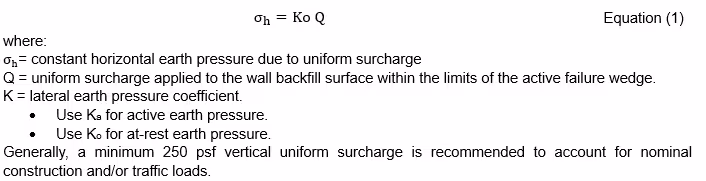
4. Uniform Surcharge
Where a uniform surcharge is present, the corresponding additional lateral pressure on the wall is a constant horizontal earth pressure. This constant earth pressure may be taken as:
4.1. Caltrans Minimum Construction Surcharge Load for Shoring
The California Department of Transportation (Caltrans) requires a minimum lateral construction surcharge σh of 72 psf to be applied to the shoring system to a depth of 10 feet (Hs) below the shoring system or to the excavation line whichever is less. This is the minimum surcharge loading that should be applied to any shoring system regardless of whether or not the system is subjected to a surcharge loading.

4.2. Caltrans Alternate Surcharge Loading (Traffic) for Shoring System
Generally, alternative surcharge loadings are limited to traffic and light equipment surcharge loads. Other loadings due to structures, or stockpiles of soil, materials, or heavy equipment will need to be considered separately. The alternate surcharge loading(Traffic) consists of a uniform lateral pressure σh of 100 psf extending to the computed depth of the shoring system.
4.3. AASHTO
AASHTO LRFD Bridge Design Specifications (AASHTO) requires a live load surcharge in terms of equivalent height of soil, heq, to be applied where the vehicular load is expected to act on the surface of the backfill within a distance equal to one-half the wall height behind the back face of the wall. The equivalent heights of soil, heq, may be taken from AASHTO Tables 3.11.6.4-1 and 3.11.6.4-2 reproduced below. Linear interpolation should be used for intermediate wall heights. The wall height should be taken as the distance between the surface of the backfill and the bottom of the footing along the pressure surface being considered.

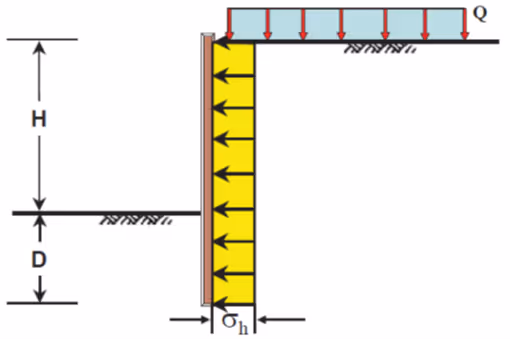
5. Point Load Surcharge
Point loads are loads such as isolated footings from adjacent structures, and outrigger loads from a concrete pump or crane. A wheel load from a concrete truck may also be considered a point load when the concrete truck is adjacent to a wall or shoring and in the process of unloading. The truck could be positioned either parallel or perpendicular to the wall. Any loads can be approximated by a point load or superposition of several point loads. A higher accuracy for corresponding lateral earth pressure requires more point loads in the approximation. The following equations may be used to determine the lateral earth pressure at a depth of h below the elevation of the point load application.
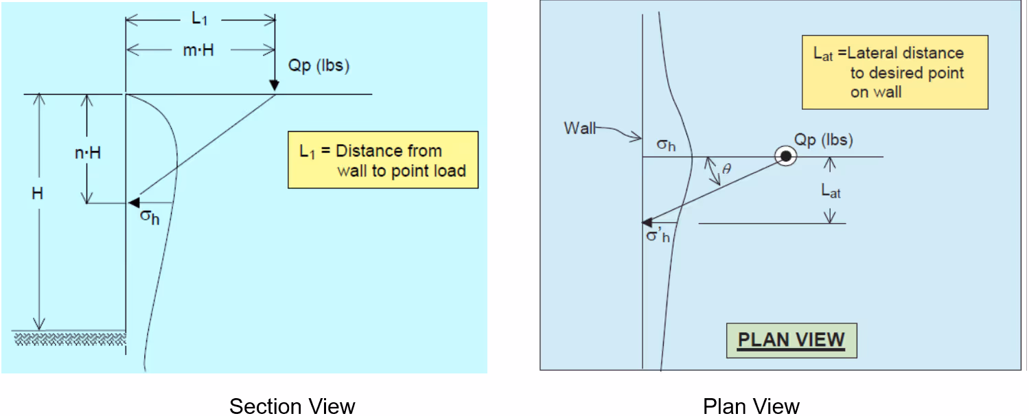
5.1. Caltrans and NAVFAC
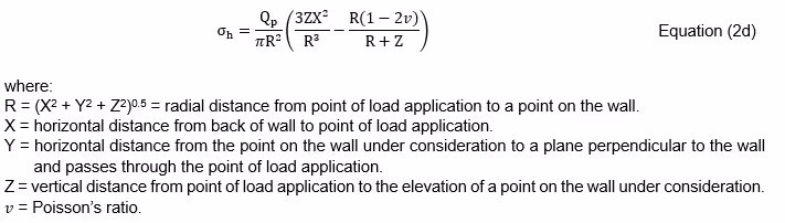
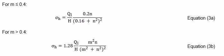
See the figures above for notations regarding m, n, H and Qp. When the point under consideration is closest to the point load Qp, the lateral pressure at the point σh can be calculated by the following equation. These equations assume an unyielding rigid wall and the lateral pressures are approximately double the values obtained by elastic solutions. The assumption of an unyielding rigid wall is conservative, and its applicability should be evaluated for each specific wall.
When the point under consideration is away from the line closest to the point load Qp, the lateral pressure σh is further adjusted by the following equation:

5.2. AASHTO
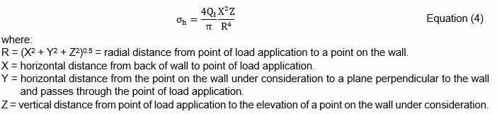
For rigid wall or walls restrained at the top, the horizontal pressure σh resulting from a point load Qp may be taken as:
6. Line Load Surcharge
A line load is a load such as a continuous wall footing of narrow width or similar load generally parallel to the wall. K-Railing could be a line load.
6.1. Infinite Line Load Parallel to Wall
For infinite line load surcharge parallel to the wall, the following equations may be used to determine the lateral earth pressure at a depth of h below the load application elevation.

6.1.1. Caltrans and NAVFAC
6.1.2. AASHTO
For rigid walls or walls restrained at the top, the horizontal pressure, σh on a wall resulting from a line load Ql may be taken as:
6.2. Finite Line Load Perpendicular to Wall
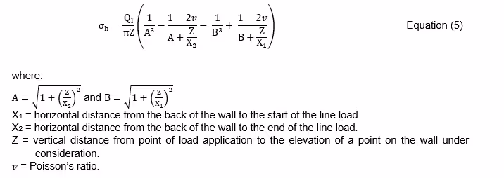
According to AASHTO, for rigid walls or walls restrained at the top, the horizontal pressure, σh on a wall resulting from a finite line load Ql perpendicular to the wall may be taken as:
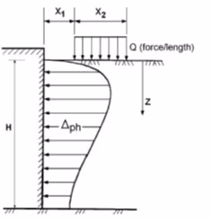
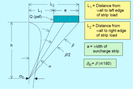
7. Strip Load Parallel to Wall
Strip loads are loads from structures such as footings that are generally parallel to the wall. According to AASHTO and Caltrans, the following equations may be used to determine the lateral earth pressure at depth of h below the load application elevation:

Based on Caltrans, for traffic surcharge in normal situations, a surcharge load Q of 300 psf spread over the width of the traveled way should be sufficient.
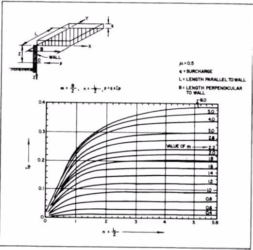
8. Uniform Rectangular Surcharge Load
According to NAVFAC 7.1, lateral pressure on a rigid wall from a uniform rectangular surcharge can be estimated from the following chart.
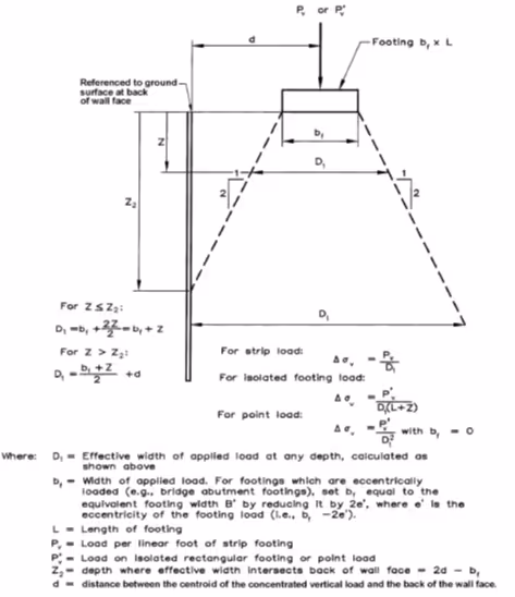
9. Point, Line, Strip, and Rectangular Surcharge Load on Flexible Wall
The above discussions (Sections 4 through 8) assume the walls are non-yielding rigid. For flexible walls, AASHTO recommends using the 2:1 (vertical: horizontal) method to estimate the vertical stress increase with depth resulting from the surcharge and then multiplying it by the active earth pressure coefficient Ka to estimate the corresponding lateral pressure. The 2:1 method is illustrated in the AASHTO LRFD manual figure 3.11.6.3-1 reproduced below.
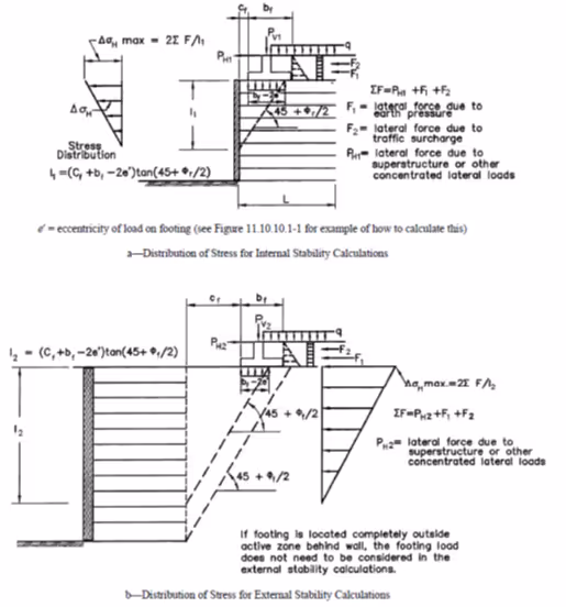
10. Horizontal Surcharge Load
For horizontal surcharge load on flexible walls, AASHTO recommends horizontal loads within the active zone behind the wall be considered. The loads should be distributed onto the wall in an inverse triangular pressure over a height of I1 or I2 as illustrated in AASHTO LRFD manual figure 3.11.6.3-2 reproduced below.
For simplicity, the 1:1 influence zone may be used for both flexible and rigid walls. This is conservative because the height of the pressure triangle is smaller and potentially more surcharge loads will be involved.
11. Pile Axial Load
Vertical stress increase around a pile may be estimated based on NAVFAC 7.1 Figure 17 reproduced below. Lateral pressure on adjacent walls can be obtained by multiplying the vertical stress by Ka and Ko for unrestrained and restrained walls, respectively.

12. General Remarks
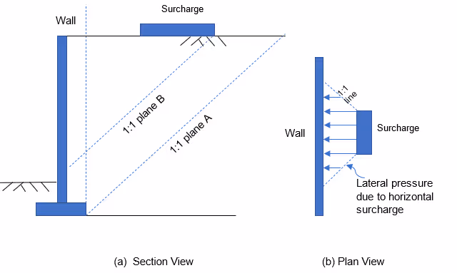
The entire vertical surcharge load within the influence zone should be multiplied by Ka (for unrestrained wall) or Ko (for restrained wall) should be considered. The entire horizontal surcharge load within the influence zone should be considered. Lateral pressure from these surcharges should be distributed onto the wall in a certain shape over a certain height and length of the wall. The influence zone may be defined by the 1:1 plane drawn up from the bottom edge of the wall footing (Plane A). The height may be determined by where the wall intersects Plane B. The length is illustrated in the plan view below. The sum of the lateral pressures due to vertical surcharge should be equal to the vertical surcharge loads multiplied by Ka and Ko for unrestrained and restrained walls, respectively. The sum of the lateral pressures due to the horizontal surcharge should be equal to the sum of the horizontal surcharge loads.
Alternatively, the vertical stress increase due to the vertical surcharge behind the wall may be calculated and multiplied by Ka (for unrestrained wall) or Ko (for restrained wall) to obtain the corresponding lateral pressure.

Dr. Liangcai He, PE, GE, brings over 32 years of experience to Twining. Liangcai has extensive experience in earthquake engineering, soil-structure interaction, field investigations, earthwork, and foundation design, retaining walls, seepage and groundwater modeling, embankment dams and levees, slope stability, and preparation of technical reports. Liangcai has performed numerous analyses and modeling for ground motion, site seismic response, liquefaction, lateral spreading, static and dynamic soil-structure interaction, system identification and optimization, slope stability and deformation, bearing capacity, elastic and consolidation settlement, lateral earth pressure, and soil springs. In addition, Liangcai is published in numerous technical papers and has peer-reviewed for the Journal of Earthquake Engineering, Canadian Geotechnical Journal, Journal of Soil Dynamics and Earthquake Engineering, IACGE International Conference on Geotechnical and Earthquake Engineering, and GeoHunan International Conference. Most recently, he was awarded the title of Outstanding Reviewer by the Journal of Soil Dynamics and Earthquake Engineering.

%20(5).png)

%20(1).png)